Crusher
In a machine parts and manufacturing class, the final project was to create a device to crush chalk. We were given a motor to use and general specifications for a 6-bar mechanism to move one of the jaws of the crusher.


The first step in designing the crusher was to obtain an estimate of the force required to crush chalk. Using vector loops and Matlab, I determined the maximum output force possible with the 6-bar mechanism. I then changed the dimensions within the mechanism so the output force was high enough to crush chalk. These calculations were used to create my original prototype.

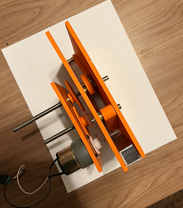
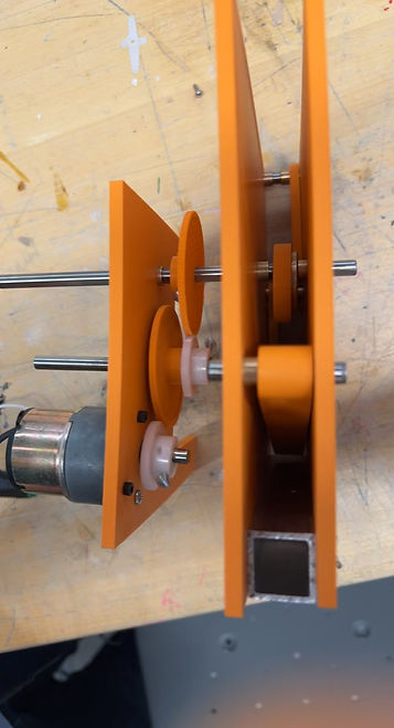
I then used the dimensions from my force calculations to make an initial prototype and study how the moving jaw worked. I decided to 3D print my initial model and used a motor to drive the assembly. There were a lot of vibrations within the system, but the initial prototype helped me understand how the mechanism moved and what needed to be fixed. I then made a second prototype using copper bushings and steel dowels to obtain a more accurate representation of how the system would function.
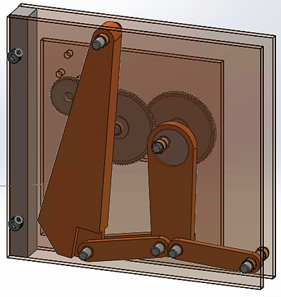

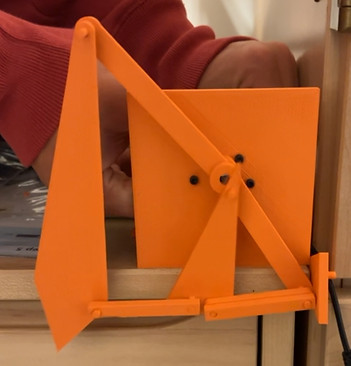
After better understanding what the system would look like, I created a CAD model of it in SolidWorks. In this design, I added a gear system to increase the output force of the crusher. I then assembled my final 6-bar mechanism. From the initial prototyping, I machined one of the links as it had the most stress on it. However, I concluded that PLA would be able to withstand the forces acting on the other links in the system. I then added the gearbox system to drive the 6-bar mechanism and finalized the prototype. The final prototype was able to crush chalk.