Plastic Shredder
For my capstone project in my final year of college, the class was divided into small groups. Each group was paired with a company from various industries. I was paired with SQ4D, a construction company that aims to automate the industry by 3D printing concrete houses.
SQ4D can currently print about 50% of the house, including the foundation and main structural elements. Their goal is to increase the percentage of a house that they are able to print. To accomplish this, they aim to shred plastic bottles of various sizes and feed these shreds into a large format plastic 3D pellet extruder to print trim, doors, and other interior accessories. To help SQ4D reach this goal, our team was tasked with creating a plastic shredder that shreds plastic to a granularity of 3-5 mm.
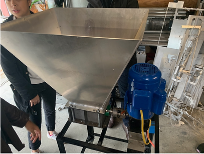

We began by going to see the shredder that SQ4D had built to see the problems it was having. The shredder that they had designed had one shaft and one stage. Some of the main problems that they were having were obtaining a uniform shred output size, and jamming (can be seen in the image above on the right). We began brainstorming and researching a design that would suit the needs of SQ4D.


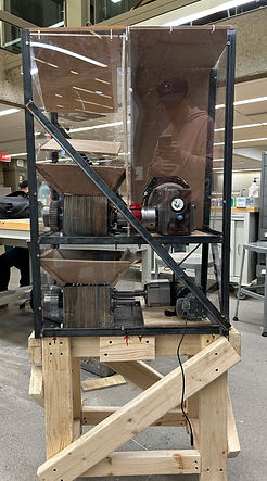
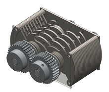
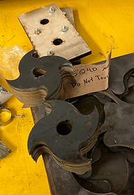
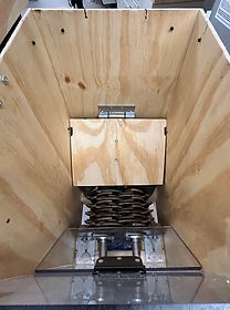
We decided to implement a two-shaft design for the shredder. The two-shaft shredder is better for grabbing material and providing an initial shred, although it is harder to get the two-shaft design to produce consistent shred sizes. To get around this obstacle, we decided to implement a second stage below the first stage to allow the material to be shredded twice before being output. I designed two different blades in SolidWorks for stage one and stage two. Stage one's blades were designed with a larger gullet and fewer knives than stage two, in order to shred the larger plastic bottles into more manageably-sized pieces. Stage 2's blades were designed to shred the plastic into finer and more consistent shreds. Additionally, we designed a multi-ramp hopper. The hopper's purpose was twofold: first, to feed bottles to the shredder and second, as a safety measure to prevent hands from being able to reach the shredder while it was operating.

Stage 1

Stage 2
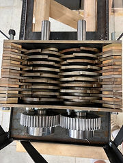
We then modeled the two blade boxes using SolidWorks. We to used ribs to help with alignment and to prevent pieces from getting stuck on the blades. For the second stage blade box (shown below on the right) we created a model with finer tolerances.


We then began to create a physical model for the first stage of the prototype. We created a model by water jetting low carbon steel for the blades, laser cutting endplates out of wood, and getting gears, bearings, and shafts off of the shelf. To verify the estimates for the horsepower of the motor we specced, we used a torque wrench to test the amount of torque required to shear a plastic bottle.
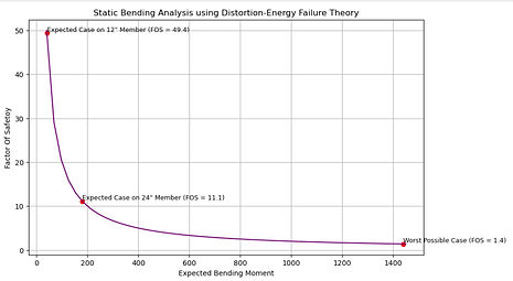
After verifying our torque calculations, SQ4D sent two motors for both stages of the shredder. We made graphs for the methods of failure we were concerned with by converting our paper calculations to Matlab and generating figures. Then we modified our design and choose materials that could support the expected loads with a reasonable factor of safety.

Once we specced out materials to use we ordered wood, steel, and angle iron. We began manufacturing parts to add ribs to the first stage of the shredder and to complete the second stage of the shredder. We started with wooden ribs that were laser cut but moved to low carbon steel ribs to maintain more consistent spacing throughout the blade box.


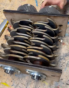
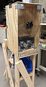
We then welded the structure that holds the blade boxes and motors and created funnels out of scrap wood so that the bottles would be fed into the blade boxes properly. We screwed the shredder down to a wooden stand to prop the lower blade box off of the ground. We were given $2000 as a budget for this project and one spider coupling that was rated for the torque requirements ended up consuming about 25% of the entire budget. For this reason we were only able to purchase one spider coupling and were only able to run one stage at a time. Therefore, we ran the blade boxes with hand cranks to test the size of the output shreds. The shred output size can be seen in the image below on the right. The shred size varied from 1/8 inch to about 1/2 an inch. To gain a more consistent output size, we planned to install a filter at the bottom of the second shredder. However, because we could not run both stages at the same time we did not include the filter. We used the built-in ClearPath software on the NEMA 56 motor that SQ4D provided to drive the first stage motor. A video of the first stage of the shredder is shown below, as well as images of the final product.